ST-1200 Line Self Ejecting

1258 Ejecting Stud Picture
Type 1258-F5xxx-Z3CT and
1258-F6xxx-Z3CT

Type 1258-F5Wxxx-Z3CT and
1258-F6Wxxx-Z3CT
Weld Plate Receptacle Picture
1224-945 Weld Plate Receptacle
S-Spring Receptacle Picture
1219-A5xxx-Z3CT and
1219-6xxx-Z3CT
Receptacle

1258 Ejecting Stud Picture
Type 1258-F5xxx-Z3CT and 1258-F6xxx-Z3CT
1258-F5xxx-Z3CT 1258-F6xxx-Z3CT
1258-F5 Dimension Drawing 1258-F6 Dimension Drawing

Type 1258-F5Wxxx-Z3CT and 1258-F6Wxxx-Z3CT
1258-F5Wxxx-Z3CT 1258-F6Wxxx-Z3CT

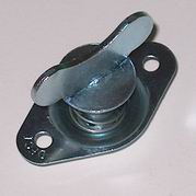
Note: For the "W" assemblies, only the wing dimensions are shown. All other dimensions are the same as the Flush Head assemblies.

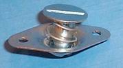
1258-F5xxx-Z3CT, 1258-F5Wxxx-Z3CT, 1258-F6xxx-Z3CT and 1258-F6Wxxx-Z3CT stud assemblies are sold with the stud and ejector spring secured in the mounting plate. The plate is riveted to the top of the removable panel, providing an advantage on weak materials by spreading stud tensile load. The extreme ejection on 1258-F5xxx-Z3CT, 1258-F5Wxxx-Z3CT, 1258-F6xxx-Z3CT and 1258-F6Wxxx-Z3CT studs is a special advantage on curved or sliding panels.


1258-F5xxx-Z3CT or 1258-F5Wxxz-Z3CT
Total
Thickness
1258 Ejecting Stud Picture
Stud
S-Spring Receptacle Picture
S-Spring
inch mm
.120-.149 3.05-3.78 1258-F540-Z3CT or
1258-F5W40-Z3CT
1219-A5275-Z3CT
.150-.174 3.81-4.42 1258-F540-Z3CT or
1258-F5W40-Z3CT
1219-A5250-Z3CT
.175-.199 4.45-5.05 1258-F540-Z3CT or
1258-F5W40-Z3CT
1219-A5225-Z3CT
.200-.224 5.08-5.69 1258-F540-Z3CT or
1258-F5W40-Z3CT
1219-A5200-Z3CT
.225-.249 5.72-6.32 1258-F550-Z3CT or
1258-F5W50-Z3CT
1219-A5275-Z3CT
.250-.275 6.35-6.99 1258-F550-Z3CT or
1258-F5W50-Z3CT
1219-A5250-Z3CT
.275-.299 6.99-7.59 1258-F550-Z3CT or
1258-F5W50-Z3CT
1219-A5225-Z3CT
.300-.324 7.62-8.23 1258-F550-Z3CT or
1258-F5W50-Z3CT
1219-A5200-Z3CT
.325-.349 8.26-8.86 1258-F560-Z3CT or
1258-F5W60-Z3CT
1219-A5275-Z3CT
.350-.374 8.89-9.50 1258-F560-Z3CT or
1258-F5W60-Z3CT
1219-A5250-Z3CT
.375-.399 9.53-10.13 1258-F560-Z3CT or
1258-F5W60-Z3CT
1219-A5225-Z3CT

Flush Head

Stud G (Grip) Weight
inch mm lb g
1258-F540-Z3CT .400 10.16 .0150 6.80
1258-F550-Z3CT .500 12.70 .0179 8.12
1258-F560-Z3CT .600 15.24 .0204 9.25

Wing Head

Stud G (Grip) Weight
inch mm lb g
1258-FW540-Z3CT .400 10.16    
1258-FW550-Z3CT .500 12.70    
1258-FW560-Z3CT .600 15.24    

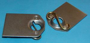
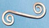
1219-A5 receptacle springs are riveted to the support. See the1219-A5 receptacles page for complete specifications, including finish.

The available receptacles for the 1258-F5 are limited to 1219-A5 springs and the 1224-945 weld plate shown below.

1258-F6xxx-Z3CT
Total
Thickness
1258 Ejecting Stud Picture
Stud 1258-F6xxx-Z3CT
or 1258-F6Wxxx-Z3CT
S-Spring Receptacle Picture
S-Spring
(inch) (mm)
.240-.264 6.10-6.71 1258-F650-Z3CT or
1258-F6W50-Z3CT
1219-6275-Z3CT
.265-.289 6.73-7.34 1258-F650-Z3CT or
1258-F6W50-Z3CT
1219-6250-Z3CT
.290-.314 7.37-7.98 1258-F650-Z3CT or
1258-F6W50-Z3CT
1219-6225-Z3CT
.315-.339 8.00-8.61 1258-F655-Z3CT or
1258-F6W55-Z3CT
1219-6250-Z3CT
.340-.364 8.64-9.25 1258-F655-Z3CT or
1258-F6W55-Z3CT
1219-6225-Z3CT

Flush Head

Stud G (Grip) Weight
inch mm lb g
1258-F650-Z3CT .500 12.70 .0290 13.15
1258-F655-Z3CT .550 13.97 .0302 13.70

Wing Head

Stud G (Grip) Weight
inch mm lb g
1258-F6W50-Z3CT .500 12.70    
1258-F6W55-Z3CT .550 13.97    

1219-6 receptacle springs are riveted to the support. See the 1219-6 receptacles page for complete specifications, including finish.

The available receptacle for the 1258-F6 is limited to the 1219-6 spring.


Weld Plate Receptacle Picture
1224-945 Weld Plate Receptacle

The 1224-945 weld plate has a stud entry hole especially designed to accept the 1258-F5 stud assembly. Extra length permits bending to fit a variety of applications.

Weld Plate Receptacle Dimension Drawing

Plate Material and Finish: Un plated cold rolled steel.

Total
Thickness
1258 Ejecting Stud Picture
Stud 1258-F5 or
1258-F5W
Weld Plate Receptacle Picture
WeldPlate
inch mm
.032-.064 .81-1.63 1258-F540-Z3CT or
1258-F5W40-Z3CT
1224-945-360
.065-.089 1.65-2.26 1258-F540-Z3CT or
1258-F5W40-Z3CT
 1224-945-335
.090-.114 2.29-2.90 1258-F540-Z3CT or
1258-F5W40-Z3CT
1224-945-310
.115-.139 2.92-3.53 1258-F540-Z3CT or
1258-F5W40-Z3CT
1224-945-285
.140-.164 3.56-4.17 1258-F550-Z3CT or
1258-F5W50-Z3CT
1224-945-360
.165-.189 4.19-4.80 1258-F550-Z3CT or
1258-F5W50-Z3CT
1224-945-335
.190-.214 4.83-6.44 1258-F550-Z3CT or
1258-F5W50-Z3CT
 1224-945-310
.215-.239 5.46-6.07 1258-F550-Z3CT or
1258-F5W50-Z3CT
 1224-945-285
.240-.264 6.10-6.71 1258-F560-Z3CT or
1258-F5W60-Z3CT
 1224-945-360
.265-.289 6.73-7.34 1258-F560-Z3CT or
1258-F5W60-Z3CT
1224-945-335
.290-.314 7.37-7.98 1258-F560-Z3CT or
1258-F5W60-Z3CT
 1224-945-310
.315-.339 8.00-8.61 1258-F560-Z3CT or
1258-F5W60-Z3CT
 1224-945-285
Weld Plate
Part Number
Plate
Dimension "H"
inch mm
1224-945-285 .285 7.24
1224-945-310 .310 7.87
1224-945-335 .335 8.51
1224-945-360 .360 9.14
Typical Installation
Weld Plate Assembly Drawing

For additional Self-Ejecting options, follow the link below to the appropriate size Stud Page

Size 3 Size 4 Size 5