ST-1200 Line
Quarter Turn
Guide Pin Fasteners
 Manufactured in the United States of America! |
|
| Studs |
1224-936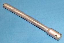
|
1224-936A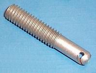 
|
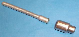
Guide Pin or Anchor-Cam Quarter Turn studs have threaded ends which may be anchored in blind holes with thread locking compound or secured to supports with lock nuts. Once installed, the studs act as guide pins, aligning the panel for locking with Anchor-Cam Receptacles.
Material: Steel, heat treated
Finish:
The above mentioned finish will be supplied as the standard finish upon depletion of existing stock which are finished as follows:
Different thread sizes, lengths, and materials are available on special order.
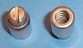
| Receptacle - Type 1224-935SL |
|
|
The compact Guide Pin receptacle is all stainless steel. It contains a heavy coil spring bridged by a cross-pin which engages the spiral cam in the stud end. The receptacle locks and releases in a quarter turn. The receptacle head has a 0.062" (1.57 mm) slot.
Material: All parts are stainless steel.
| Locked tension: | 60 lb |
| Receptacle locking torque: | 15 in-lb |
| Receptacle unlocking torque: | 10 in-lb |
| Rated tensile strength: | 500 lb |
| Ultimate tensile strength: | 1,000 lb |
| Installation |
| Installation procedure using thread locking compound |
- Lock the receptacle onto the stud cam.
- Coat both the stud and hole threads with locking compound.
- Thread the fastener assembly down into the hole until it is tight. Refer to figure 1.
- Back the assembly out for one full turn, then allow the compound to cure before using.
|
Figure 1: Blind hole mounting using thread locking compound |
|
|
Figure 2: Stud secured from behind using a lock-nut |
|
|
Figure 3: Blind hole application using a jam nut |
|